
Comparison of Ancient Carts and Roman Transportation on Land and Rivers
(State: 28.03.2026)
Another field of investigation concerns ancient transportation (on streets and rivers), whose products are available in reliefs and individual finds, but are also described in historiographical writings. Here, therefore, reconstruction according to the guidelines and a comparative test are possible, with the aim of evaluating findings on the close relationship between infrastructure and technology.
Reconstructed types include a Celtic multi-purpose cart with rims out of one solid beam and longitudinal suspension, a Roman two-axle cart with segmented rims and transverse suspension, and a Roman racing cart, found in a grave in Croatia 2021. The empirical findings after construction include (as things stand):
a) the differences in ride comfort, manoeuvrability, and material and draft animal stress, which give the Celtic wagon construction of this type an advantage.
b) findings about the connection between road infrastructure and wagon construction, which required the respective production sites to satisfy “customer demand.”
The challenges of cart construction in pre-Roman and Roman times are related to the existing infrastructure. This explains why sophisticated but also complex techniques in cart construction fell out of use after the Romans conquered the Celtic settlement area (probably roller bearings included). In Roman times, more effective forms of cart construction became established on the standardized road network of the Roman province in Gaul, while older forms of cart construction remained in use in the unconquered Celtic retreat areas.
The Celts used chariots as weapon against their opponents (for example Caesar, De Bello Gallico 4.33: 54 BC) when the other Mediterranean peoples had long since ceased to have these chariots as a type of weapon or even despised them (Vegetius).
Long before 500 BC (Hallstatt period), the troops of the Celts, whose influence extended from Ireland in the northwest to central Asia Minor, had this battle weapon. After 500 BC (La Tène period), the single-axle, light, fast chariots increasingly dominated among the Celts. Their troops charged fearsomely against Roman armies in northern Italy in the third century (Polybios, Livy). Like Homer's heroes, the Celtic chariots drive their fighters up to the enemy line-up, the fighters jump off and fight and are picked up again by the charioteers, who enjoy a high status among the Celts (Diodorus Siculus 5.29) as do the charioteers of Homer. According to Tacitus, the leader of the revolt of Celtic tribes against the Romans in Britain, Boudicca, travelled in a fast chariot to coordinate the uprising in the first century AD (Annales 14.35-37). The art of chariot making and its drivers were still held in high esteem in Irish legends in medieval times when their outstanding achievements in other areas had fallen out of practice since the Roman conquest.
Not only a status symbol, a luxurious means of transportation and a battle utensil (Athenaeus 4.152 and Pliny the Elder Naturalis Historia 34.162-163), carts also accompanied the nobles into their ‘next’ life in the grave: there we have the best evidence of a relatively uniform chariot culture, with specific features: on the single-axle chariots, the driver sat at the front without cladding and steered, there was protection at the sides, the wheels were bent 360 degrees from an ash tree – and they had longitudinal suspension. Although the Celts had a well-developed road system, especially near settlements and across rivers and moors, it was not on a par with the Romans. As a result, the route was often cross-country and the noble Celtic lords and ladies wanted comfort. The construction of a single-axle carriage followed the find in La Tène (end of the 19th century), which was also the model for Furger's reconstruction (1993/2021).

Fig. 23: The rim out of one (see arrow for the sole seam) beam of ash-wood. Photo by B. Dreyer.
He surpassed competing attempts, most recently that of Metzler (1986), who reconstructed a longitudinal suspension for the first time and wanted to use the double eyelet pins for this purpose. Furger, who ultimately delegated wheel-production to a wainwright, perfected this suspension by using forks on which the carriage body rested. This reconstruction is recognized as the best (Stifter and Karl, 2011) and is also superior to that of the British Museum from 2003, which is based on a Y-suspension attached to the side.
The FAU-construction had to overcome the first hurdle by bending an ash rim/wheel (figures 23 and 24), which would later have a diameter of 90 cm, from a straight state (about 50 mm wide, 50 mm high and 3 m long). Today's wainwrights only know segmented wheels. So we had to test it ourselves: The plank had to boil in water for more than 12 hours, then the ash was soft enough to be bent, with the appropriate pressure.
Fig. 24: One of the many bending tests after boiling the ash plank for over 12 hours. Photo by B. Dreyer.
Together with the hubs and the spokes, these rims, flat butted, without pins, formed a solid unit, especially after the iron tire was shrunk on.
The axle, 180 cm long in total, holds the compact wheels; an axle pin prevents the wheels from running off. The drawbar is inserted between the axle and the axle support. The forks, which are bent upwards (by steam bending), are central to the longitudinal suspension. They extend from the axle, attached to it under the charioteer's platform – this was Furger's achievement. At their ends at the backside, ropes are pulled through eyelets, which are guided forwards in a triangle around a wooden block fixed to the drawbar (bent upwards by steam bending) in front of the platform and tensioned with a toggle at the bottom of the wooden block (see figure 25). Here the rectangular chariot platform comes to rest fixed on the triangle of ropes tensioned by the forks and drawbar, thus absorbing the shocks of the tires on the uneven ground. Nevertheless, the platform is fixed in its position by the eyelets which are passed through the platform rims from above. This provides comfort for the driver and horses, which are harnessed and guided in pairs via a yoke.
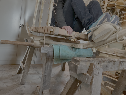
Fig. 25: Suspension by ropes led from the bent forks at the rear right and left to the front in the triangle and under the box body through eyelets and stretched over the footboard at the front with toggles. This lightweight vehicle is highly maneuverable, weighing barely 100 kg and yet robust. Photo by. B. Dreyer.
| Carriage components | Dimensions |
| Hub with hub rings | diameter maximum 20 m, width 39 cm |
| Spokes | 29 cm without tips |
| Axle |
180 cm long, axle with 6 cm diameter included 12.5 cm maximum high |
| Axle support | 116 cm long |
| Rim/wooden wheel | 50 mm x 50 mm x 282 cm (diameter: 90 cm) |
| Iron tire | 6 mm x 40 mm |
| Plattform | 132 cm x 95 cm |
| Drawbar | 232 cm (bent upwards by about 30 degrees) |
| Fork | 140 cm bent |
| Yoke | 100 cm |
| Track width | 124 cm |
| Total weight | 98.7 kg |
Table with dimensions
We adopted the longitudinal suspension from Furger (1993/2021), but banned the double eyelet pins: as a result, the wagon is truly horizontal, as all the illustrations of antiquity show, because the platform can be positioned further back. Furthermore, this omission makes the Celtic wagon easy to dismantle, an important principle in this construction tradition, so that the highly complex wagon structure was easy to repair. However, our tests with Haflingers or Ponys (in the size of antique horses) will have to show what these carriages can achieve in comparison to Roman carriages (which had at best a traverse suspension and segment rims), which our team now wants to build in cooperation with the „Freilichtmuseum am Kiekeberg" Hamburg.

Fig. 26: Celtic chariot. Photo by B. Dreyer.
The Roman Empire developed long-distance roads. These roads were built immediately after conquest to facilitate Roman armies, trade and all other forms of communication.
People could travel in different ways, on horseback, in two-horse open carriages or in covered coaches–as in many other areas, the Romans benefited from what the cultures they conquered had to offer and integrated this into their own knowledge: For example, the Romans adopted many Celtic terms, such as carruca for the travelling carriage. The travelling carriages certainly varied greatly in design, depending on the comfort requirements and the person being transported. Travelling was not always a pleasure (heat: Pliny the Younger, Epistulae 10.15), but it could also offer a pleasant place of ‘seclusion’ (for conversations: Martial, Epigrams 12.24; for eye ailments: Pliny the Younger, Epistulae 7.21). Little is known about their appearance. The most important evidence is the relief from Maria Saal in Lower Austria (figure 27).

Fig. 27: Carruca relief embedded in the wall of the church in Maria Saal, Austria. Photo by J. Jaritz 2023 (license: CC BY-SA 4.0. Available at: https://de.wikipedia.org/wiki/Datei:Maria_Saal_Dom_Grabbaurelief_Reisewagen_in_die_Unterwelt_ 29062007_02.jpg [Accessed 23 Marc 2026].
Such illustrations and finds of cart fragments leave room for interpretation. There have been several replicas. The most famous are the replicas from the Romano-Germanic Museum in Cologne (based on the Wardatal finds) and the one from Colonia Ulpia Traiana in Xanten (Held, 2020, pp.113-133).
The Cologne replica has interesting interpretations, but these cannot be verified in the relief or contradict this relief. These include the downwardly narrowing floor, which allows for a wider front axle and thus a smaller turning circle. This, as well as some of the design features (modern tongue-and-groove flooring and coachman's seat), make this reconstruction appear inferior to the one from Xanten when viewed from a scientific perspective (R. Grüßinger, scientific advisor at the Römisch Germanisches Museum Cologne (email 14 April 2025).
The reconstruction of Xanten has been discussed in detail and also tested. However, the construction and thus the equipment are largely determined by the wagon factory in Poland that carried out the work. The iron tyres, wooden rims and wheel diameter are very solid, as is the passenger compartment, which is made entirely of wood. This makes the wagon heavy. Other interpretations have been documented, such as the carriage from the Archaeological Landscape Park in the Eifel municipality of Netterheim, which was destroyed in a fire in 2021 (https://archaeologischer-landschaftspark.de/erleben/roemischer-reisewagen.html, last access: 12. March 2026).
What all serious replicas have in common is the so-called transverse suspension, which can be seen in the relief (Furger, 2021, pp.19-22). Its effectiveness was tested in Xanten using a vibrating board (Held, 2020, pp.131-133). However, the tests (this also applies to Bodenstein and Bräunling, 2001) provide little insight because the criteria cannot be evaluated by reference to other ancient carriages.
The construction of the FAU was based on the following principles:
1) The setting of parameters for carriage parts to enable the comparability of carriages with different suspension systems, insofar as historical conditions and evidence do not prevent this. These include hubs, axles, wheel diameters of approximately 90 cm, rim dimensions (whereby the Celtic carriage has a rim out of one solid beam and the Roman carriage has a segmented rim (compare the diameter of Xanten)).
2) The lightweight construction of the carriage body, as far as the pictorial and written specifications allow.
The track width was standardised to a certain extent (based on wheel tracks and axle findings), approximately 145 cm (compare the Xanten carriage). The segment wheels were made according to the specified dimensions (diameter 90 cm, rims 5 cm high, 5 cm wide, later shaped conical) by the Wagnermuseum am Kiekenberg near Hamburg. We shrunk the iron tires and hub rings.
Two axletrees (ash) were turned to a diameter of 60 mm. Two oak axle bolsters, which rest on the axletrees as support for the reach pole and swing hangers, were made to a length of 1 m, a height of 30 cm and a thickness of 6 cm.
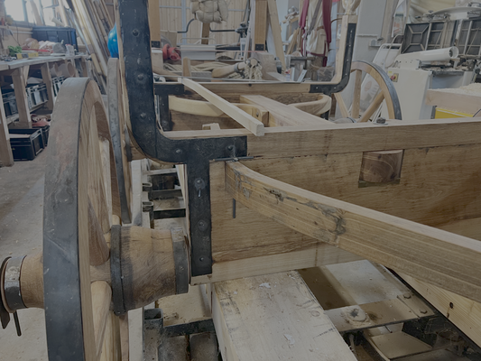
Fig. 28: View on axle bolsters and swing hangers in the background. Photo by B. Dreyer.
Two swing hangers for the rear axle are cut out of solid ash wood with a thickness of 60 mm. It was not possible to bend the rear swing hangers (unlike those on the front axle) due to the tight radii, although swing hangers bent under steam would certainly have provided greater protection against breakage. The swing hangers were fitted into the axle bolsters and secured to the reach pole with iron bolts with a diameter of 10 mm. The reach pole, made of ash wood, serves as a supporting beam between the rear and front axles and is cut to a length of 140 cm, a width of 14 cm and a height of 10 cm. Two swing hangers made of ash wood are bent under steam for the front axle to mount the drawbar.
An iron bolt with a diameter of 12 mm is installed in an iron sleeve with an outer diameter of 16 mm and a length of 30 cm as the pivot point and bearing for the front axle. Four ash chassis or frame beams, side stanchions, were fastened with wooden dowels. They are designed to support the passenger cabin suspension. Bronze uprights are inserted at the top. To stabilise the cabin suspension, a 3 mm thick sheet metal plate is bolted on both sides from the upper edge of the respective (two) axle bolsters of the front and rear axles to and over the (respective) side stanchions, which supports the bronze uprights weighing 6.5 kg each (figure 29). Since the front axle swing hangers has to bear the weight of the drawbar, a crossbar made of ash wood must be constructed on the opposite side of the front axle as a counterweight under the reach pole.
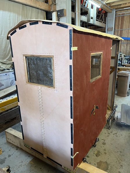
The construction of the passenger cabin begins with the floor panel. It consists of a frame measuring 2.3 m in length, 0.95 cm in width and 8 cm in height. A course correction of 90 degrees should be possible without contact. The initial relief (figure 27) argues against a higher cabin suspension to prevent contact. The side walls are covered with linen (dyed and painted using the tempera method), the front and rear walls are covered with leather (the covering is attached with several 26 cm long metal strips) and the roof is covered with tanned rawhide on curved segments.

Fig. 29: cabin with suspension. Photo by B. Dreyer.
Window openings are also provided on all four sides, two of equal size on the sides and rear wall (approximately 30x40 cm), and another at the front for communication with the coachman (approximately 15x25 cm). They are covered with yarn (fig. 29), between which very thin, translucent and smoothed rawhide (approximately 1 mm) can be inserted. For the ‘transverse suspension’ or free-hanging suspension of the cabin, leather straps lead from the four bronze uprights to the lower cabin frame, where they are attached to hooks. In this way, the cabin frame hangs freely, about 5 cm above the axle frames. This allows the cabin to move a few centimetres in the transverse and longitudinal directions. However, classic vertical spring movement is not possible in this way. The leather straps (approximately 3 mm thick) are three-layered and sewn with hemp thread soaked in beeswax. The lower ring of the leather straps on the front axle is guided in an iron rod and can slide sideways when the axle turns, thus enabling curve driving.
Window openings are also provided on all four sides, two of equal size on the sides and rear wall (approximately 30x40 cm), and another at the front for communication with the coachman (approximately 15x25 cm). They are covered with yarn (fig. 29), between which very thin, translucent and smoothed rawhide (approximately 1 mm) can be inserted. For the ‘transverse suspension’ or free-hanging suspension of the cabin, leather straps lead from the four bronze uprights to the lower cabin frame, where they are attached to hooks. In this way, the cabin frame hangs freely, about 5 cm above the axle frames. This allows the cabin to move a few centimetres in the transverse and longitudinal directions. However, classic vertical spring movement is not possible in this way. The leather straps (approximately 3 mm thick) are three-layered and sewn with hemp thread soaked in beeswax. The lower ring of the leather straps on the front axle is guided in an iron rod and can slide sideways when the axle turns, thus enabling curve driving.
Fig. 30: Carriage body with antique-painted linen on the sides, leather back and front walls, with rawhide roof. Photo by B. Dreyer.
Passenger compartment weight 128 kg, including: chassis without wheels and without drawbar 93 kg, 1 wheel 21 kg, x 4 = 84 kg, 4 windows approximately 1 kg, door linen blind 2.5 kg, 2 linen covers 5.0 kg, strip iron 16 kg, leather front and rear covers, tanned leather roof: 5 kg.
A find in Croatia from 2020 is set to expand the test spectrum. It is a Roman chariot that will be compared with the capabilities of the Celtic chariot. Results, in cooperation with the Croatian excavators (Hrvoje Vulic) are expected in 2026, including the tests.
Supplying military fortresses and their civilian settlements near the border was a top priority for the Roman provincial administration in the region along the so-called wet and overland limes. However, the most effective supply was by water on the rivers along the border or to the border. The means of transport were barge boats, which, with their shallow draught, could navigate even the smallest rivers, depending on their meandering course, and in a wide variety of lengths (from 10 to 35 metres, maximum draught of 1 m, maximum width of 6 m) and could carry several tons (between 7 and 80 tons load capacity, compare animals with a maximum load of 135 kg or animals pulling carts with max. 650 kg) to supply entire legions for days, weeks and years. Towed, rowed or poled, assisted by a sail, the barges could travel about 15 km per day upstream and 20 km downstream on a river such as the Lippe.
A legion needed 5 tons per day, 1800 tons per year of grain alone, not including luxury goods and weapons (Jaschke, 2009, pp.197-199). This is documented for the Lippe, for example, by the construction of paths along the riverbank, which ensured that these ships could be pulled.
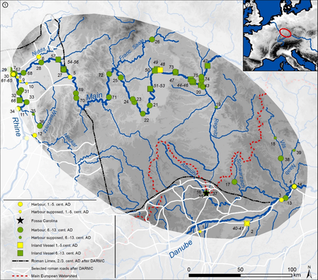
Fig. 31: Altmühl-river and Roman Limes. Illustration by L. Werther (Dreyer, Sponsel-Schaffner, Hilverda, Werther, 2021, p.39).
This is also likely for the Altmühl-river (figure 31), which supplied the camps at Gnotzheim and Theilenofen and Gunzenhausen, with a total of around 1,000 men and a requirement of one ton of wheat per day. The Gunzenhausen fort was located at a ford on the Altmühl, which crossed the Raetian Limes to the north-west and thus left the Roman Empire (Dreyer, Sponsel-Schaffner, Hilverda and Werther, 2021, pp.36-38). Barges with a length of about 10 metres would have been able to travel with a load of about 7-8 tons along the meandering Altmühl to the Raetian Limes near Gunzenhausen. According to accounts from the Napoleonic era, from Graben (site of the Fossa Carolina from 798 AD) onwards, the Altmühl had sufficient water flow for ship transport of up to 8 tons. The distance between Graben and Gunzenhausen upstream is 15 km, about a day's journey on the slow-flowing Altmühl.
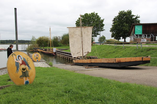
Our model was the Prahmboot II from Zwammerdam in the Netherlands (figure 32), which has been replicated several times. Once again, we wanted to stay close to the original using traditional methods, tools, techniques and materials.

Fig. 32: Finding and reconstruction plan of M.D. de Weerd 1988.
- Our barge, the Alchmona rediviva (medieval rendering of Altmühl), was modelled on De Weerd's plans, on a scale of 1:2. This does not prevent any insights (see De Weerd, 2001, p.105), but it did correspond to our limited supply of wood and the dimensions of the shipyard. The joints have all been caulked with hemp thread and then tarred. We have applied a wood preservative varnish up to the assumed waterline. The boat is therefore 11.05 m long (front ramp 2.55 m, rear ramp 1.35 m). It is up to 54 cm high and 165 cm wide at its widest point. It is expected to have a load capacity of around 7 tons. This is actually beneficial for the test conditions in or capacity of the Altmühl-river.
- The oak frames, which are alternately aligned to port and starboard, are fastened to the floorboards with bent iron nails (approximately 600 in total in the boat, from the outside to the inside), to fix the floorboards to the L-shaped sides by means of frames at larger intervals (here according to the ‘frame/skeleton first’ construction method), but according to the ‘shell-first’ principle. After that, the remaining frames were inserted in phases, halving the distances (up to phase IV, see De Weerd, 2001, p.107). Both knees and forks were attached at the top of the second, clinker-built side plank by a counter-nailed batten, as far as they reached the board, 42 times according to the model. Iron cramps stabilised the ramps at the front and rear, as in the prototype; a keel block 5 m long, maximum 9 cm high and 5 cm wide, thickened in the middle to 12 cm for the mast shoe at 80 cm, serves as longitudinal stabilisation in accordance with the prototype.
The launch happened 23 September 2025. Tests will be carried out with the boat on the Altmühl to determine its transport and manoeuvring potential (by poling, pulling and sailing).
Literature:
Ancient carts in comparison, transportation on rivers
- Andrikopoulou, J-N., Held, S., Jäger, J., Jaschke, K. and Schmidhuber, G., 2020. Auf Achse mit den Römern: Reisen in römischer Zeit. Oppenheim: Nünnerich-Asmus Verlag & Media.
- Bodenstein, W., Bräunling, A.R., 2001. Keltischer Kampfwagen – nachgebaut und erprobt. Archäologie in Deutschland 2, pp.60-63.
- Bockius, R., 2000. Antike Prahme. Monumentale Zeugnisse keltisch-römischer Binnenschiffahrt aus der Zeit vom 2. Jh. v.Chr. bis ins 3. Jh. n.Chr. Jahrbuch des Römisch-Germanischen Zentralmuseums Mainz 47(2). pp.439-493.
- De Weerd, M.D., 1988. Schepen voor Zwammerdam. Bouwwijze en herkomst van enkele vaartuigtypen in Westen Middeneuropa uit de Romeinse tijd en de Middeleeuwen in archeologisch perspectief. Proefschrift. Universiteit van Amsterdam.
- De Weerd, M.D., 2001. Römische Schiffsfunde von Zwammerdam. Lehren aus einer alten Grabung. Skyllis 4. pp.96-110.
- Held, S., 2020. Vom Reißbrett auf die Straße - die Rekonstruktionen römischer Kutschen im LVR-archäologischen Park Xanden. In: Andrikopoulou, J-N., Held, S., Jäger, J., Jaschke, K. and Schmidhuber, G., 2020. Auf Achse mit den Römern: Reisen in römischer Zeit. Oppenheim: Nünnerich-Asmus Verlag & Media. pp. 99-133.
- Jaschke, K., 2009. Tonnenweise Getreide. Die Versorgung der römischen Legionslager an der Lippe. In: R. Aßkamp, ed., 2009. 2000 Jahre Varusschlacht, Volume 1: Imperium. Darmstadt: WBG. pp.196-202.
- Metzler, J., 1986. Ein frühlatenezeitliches Gräberfeld mit Wagenbestattung bei Grosbous-Vichten. Archäologisches Korrespondenzblatt 16. pp.161-177.
- Stifter, D. and Karl, R., 2011. Carpat - Carpentum: Die keltischen Grundlagen des „Streit“wagens der irischen Sagentradition. In: A. Eibner, R. Karl, J. Leskovar, K. Löckner and Chr. Zingerle, eds. 2011. Pferd und Wagen in der Eisenzeit - Akten zur Tagung in Wien, 23. - 26. Februar 2000. Wiener Keltologische Schriften, Volume 2. Wien: Wiener Universitätsverlag WUV.
- Furger, A., 1993. Nachbau eines essedum im Schweizerischen Landesmuseum. Zeitschrift für Schweizerische Archäologie und Kunstgeschichte 50. pp.213-221.
- Furger, A., 2021. Der gefederte keltische Wagen und seine kulturgeschichtliche Einordnung [pdf] 2nd ed. Available at: <https://andresfurger.ch/images/2021/11/C2a-Andres-Furger-Der-gefederte-keltische-Wagen-und-seine-kulturgeschichtliche-Einordnung.pdf> [Accessed 20 March 2026].
- Röhring, Chr. W., 1983. Untersuchungen zu römischen Reisewagen, Koblenz: Forneck.
- Barth, F.E., 1987. Vierrädrige Wagen der Hallstattzeit. Untersuchungen zu Geschichte und Technik. Mainz: Verlag des Römisch-Germanischen Zentralmuseums.
- Dreyer, B., Hilverda, A., Sponsel-Schaffner, Chr. and Werther, L., 2022. Identifying Research Gaps for a Comprehensive Presentation of the Roman Danube Limes. 4.1 Germany: Navigability of Rivers in Roman Times and Roman Navigation on the River Altmühl. Some Remarks and Research Perspectives. In: Danube Transnational Programm, Living Danube Limes, 2022. Deliverable D.T1.2.1. Identification of Potential of Historical Roman Story Telling. pp.37-48. Available at: <https://dtp.interreg-danube.eu/uploads/media/approved_project_output/0001/46/dc2689c1ed48ad10458c755823f451077f0a3877.pdf> [Accessed 20 March 2026].
- Dreyer, B., 2026. Longitudinal Suspension and Bent Rims. Cross-Country Celtic Chariots. Ancient Warfare 105. pp.54-57.
- Dreyer, B., 2026. Roman Cargo-Boats (Prahm). Ancient Warfare 107 [in print].